Hardware
Block Level Design
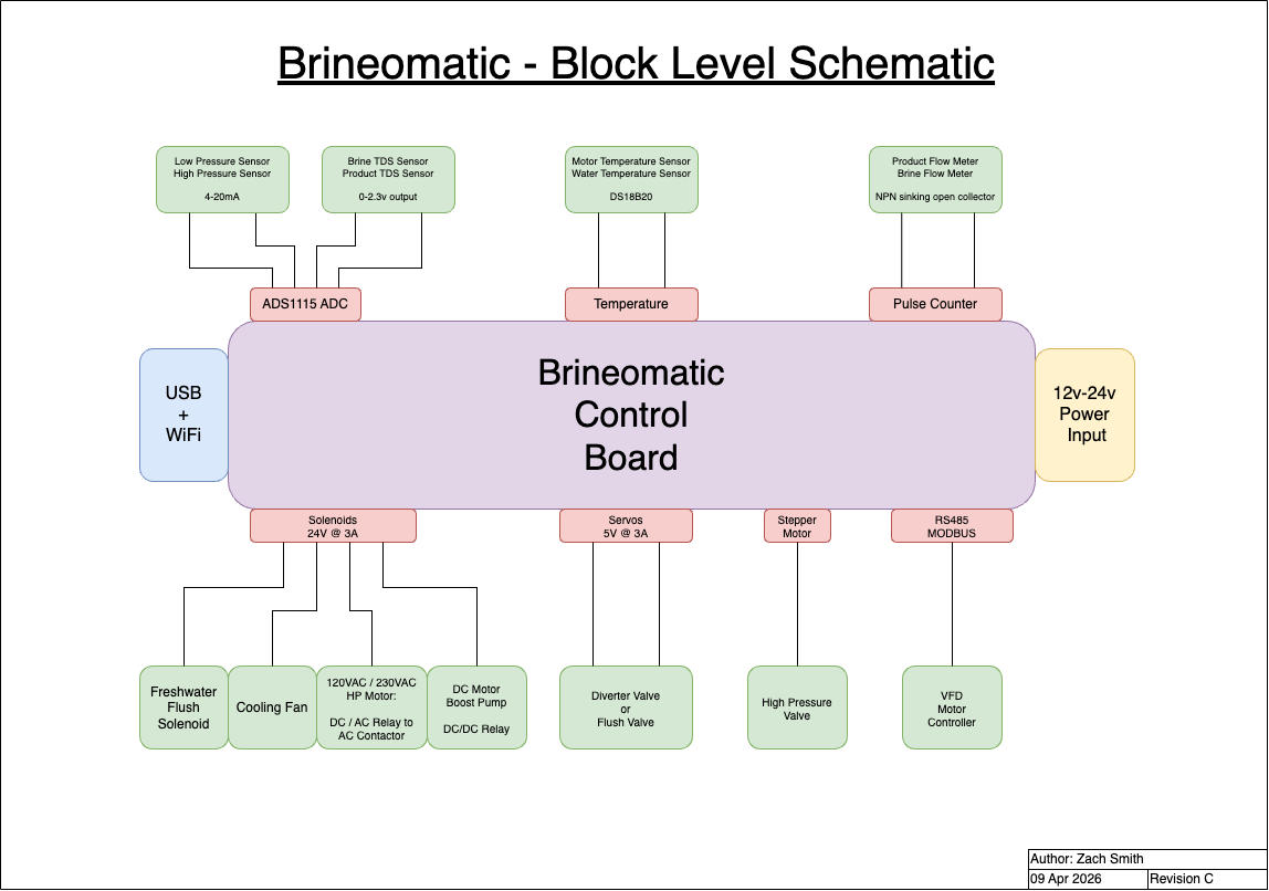
Sensors and Actuators
Brineomatic is designed to be compatible with a wide variety of different hardware. Please see the Sensors and Actuators page for full details.
Where To Buy
Details on how to get Brineomatic here
Revisions
- Revision C — latest version
- Revision C1 is fully compatible with only minor silkscreen and part changes
- Revision B - prototype with stepper motor and other upgrades
- Revision A - first prototype with 1000+ hours and 100k liters produced
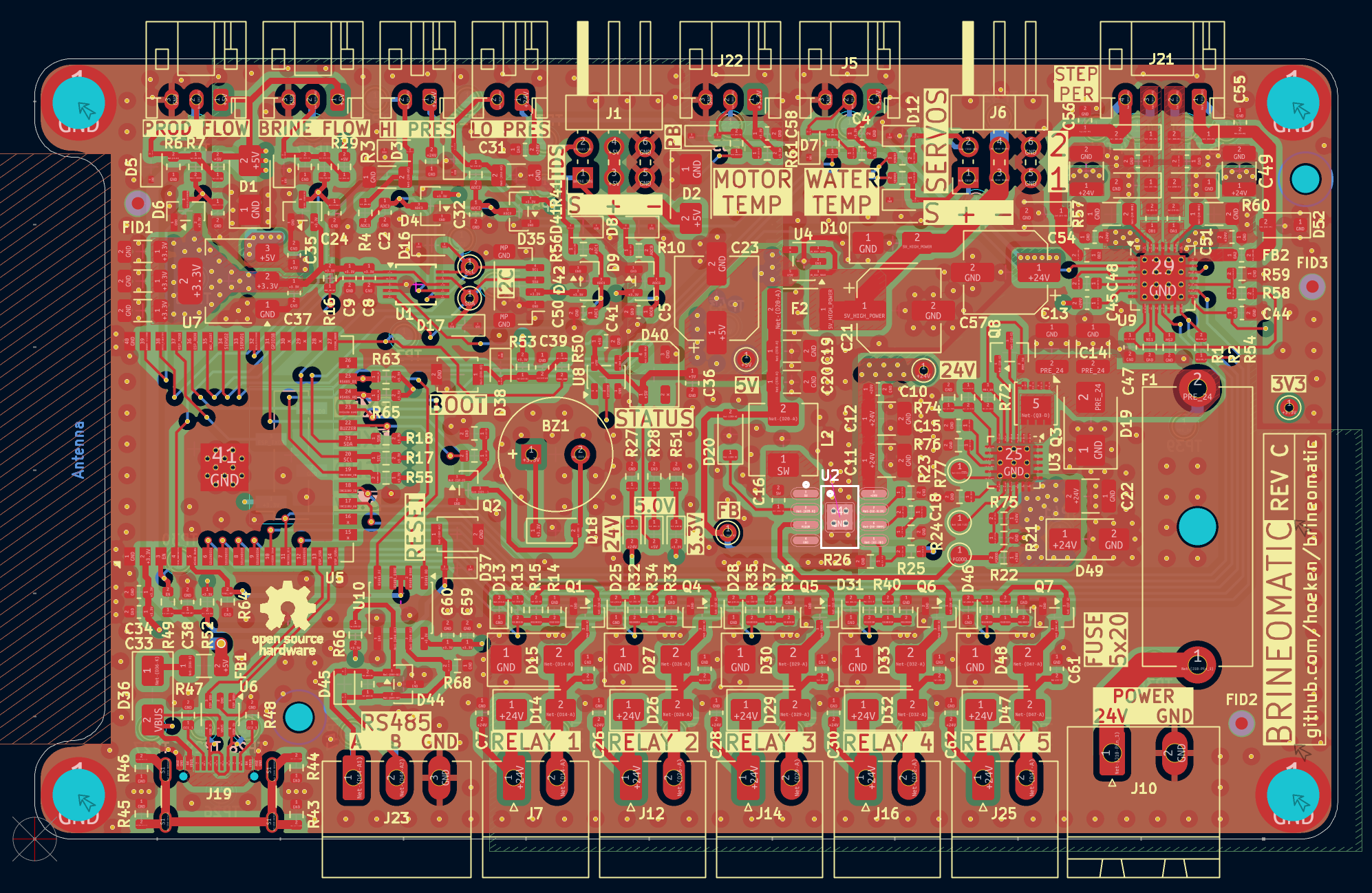
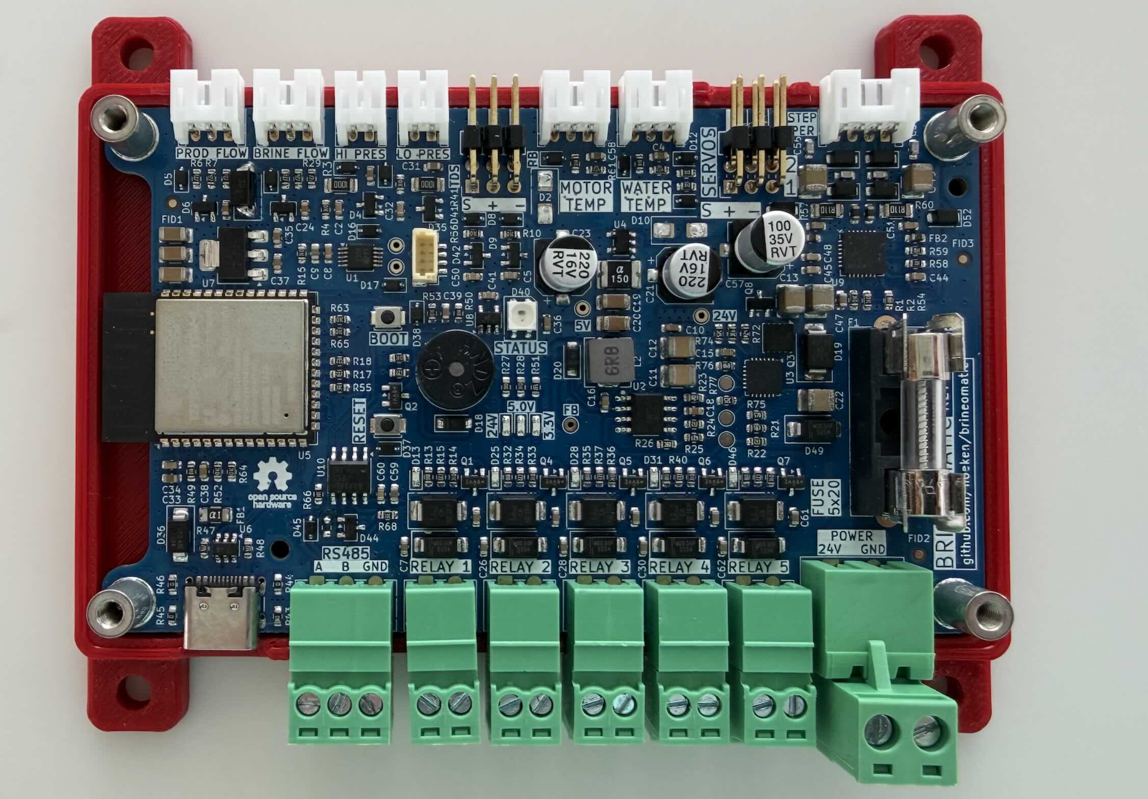
Brineomatic hardware is fully open source and licensed under the Open Hardware License (OHL) license.
All hardware design files (schematics, gerbers, and BOM) are available on GitHub.
Changelog
Brineomatic Rev C1
- Fixed SMAJ5.0A symbols and footprint
- Swapped L2 and L3. Now SIG/GND/PWR/SIG
- Fixed Water/Motor Temperature silkscreen mixup
- Re-routed 5v to run through TVS first
- Increased 5v fuse to 2.6A
- Marked R67 (RS485 termination resistor) as DNP
Brineomatic Rev C
Power System & Protection
- Power Protection: Switched to TPS26630 for main power protection.
- Regulators:
- Switched to RT7272B for 24V -> 5V regulation.
- Switched to LDL1117 LDO for 5v -> 3.3V regulation.
- Changed
ESP32_5Vto 5V to allow powering the entire board over USB except servos.
- ESD & EMI:
- Comprehensive ESD protection added to all power rails (24V, 5V, 3.3V).
- Added ESD protection to relay driver connectors, analog sensors, and GPIO0/EN.
- Added 470pF/100V caps, inductors, and TVS to TMC2209 outputs.
- Added 1uF caps to pressure sensor connectors.
- Implemented USB shield grounding (2x0 ohm resistors).
- Filtering:
- Added bulk capacitors after ideal diode and on the 5V rail.
- Added bootstrap diode.
- Configured voltage divider on EN pin to turn on at 10.2V (hysteresis).
- Changed USB fuse to 1.5A.
Circuit Design & Components
- MOSFETs:
- Swapped AO3400A for Si2318 to provide more headroom for 24V supplies.
- Changed gate resistors to 220Ω and pulldowns to 10kΩ.
- Moved switch pulldowns before the 220Ω resistor (removed voltage divider effect).
- Sensors:
- 4-20mA Sensors: Changed sense resistor from 165Ω to 100Ω to better optimize ADC range.
- Analog Inputs: Added inline 100Ω resistors to temperature sensors and servo inputs. Switched to BAV199 diodes for protection on Pressure/TDS inputs.
- Peripherals:
- RS485: Added MAX-485 circuit with termination resistor.
- Buzzer: Switched to Huaneng QMB-09B-03 piezo buzzer + diode.
- Steppers: Removed VREF circuitry from TMC2209 driver; improved 24V routing.
- Relays: Added an extra relay/solenoid output.
PCB Layout & Mechanical
- Connectors:
- All connectors aligned flush with the 3mm outside edge of the case.
- Added backup USB serial converter headers.
- Added dedicated water temperature connector.
- Stacked TDS inputs.
- Routing:
- Complete re-route of the board (Rev C).
- Optimized Ground planes and L2 -> 24V / 5V / 3.3V power plane.
- Re-arranged pins to avoid boot glitches on solenoids.
- Test Points:
- Added 1.5x0.7mm test points for 3.3V, 5V, 24V, GND, SDA, and SCL.
- Added test points to bottom of board for potential functional testing/
- Silkscreen: General cleanup, legibility tweaks, and documented pinouts.
- Mechanical: Widened attachment points.
Documentation & Firmware Support
- Updated pinout documentation and cropped diagrams.
- Added Node-RED flow examples and running mode.
- Verified BOM and CPL files for production.